A band stop filter is a frequency filter that stops the frequencies inside a frequency band and passes the frequencies that are below and above that band.
Example band stop filter and sound sample
See Orinj Band stop filter to hear a sound sample before and after a band pass filter.
Example magnitude response of a band pass filter
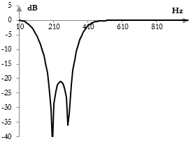
The following is an example magnitude response of a band stop filter. This filter reduces the magnitudes of frequencies between 100 Hz and 350 Hz in the signal and leaves the magnitudes of frequencies below 100 Hz and above 350 Hz approximately at their original level.
The opposite of a band stop filter is a band pass filter.
A band stop filter with a very narrow stop band is called a notch filter.
Finite impulse response digital band stop filters
The following is the formula for a finite impulse response (FIR) band stop filter.
$$a(k)=\begin{cases} -\frac{ \sin(\frac{2\pi f_1 (k-\frac{N-1}{2}}{f_s})}{\pi (k-\frac{N-1}{2})}+\frac{ \sin(\frac{2\pi f_0 (k-\frac{N-1}{2}}{f_s})}{\pi (k-\frac{N-1}{2})}, & k \ne \frac{N-1}{2}\\ 1-2\frac{f_1}{f_s}+2\frac{f_0}{f_s}, & k = \frac{N-1}{2}\end{cases}$$
Here, N is the length of the filter. f1 and f0 are the cutoff frequencies at the top and bottom end of the stop band respectively. fs is the sampling frequency.
A band stop filter can thus be created by simply subtracting the output of a band pass filter from the output of an all pass filter. The FIR band pass filter itself is the difference between two low pass filters – one at the top cutoff frequency and one at the lower cutoff frequency.
Practical band stop filters are not ideal, as they do not completely eliminate frequencies in the stop band, may have ripples in the pass bands, and have a slow transition between the stop band and pass bands. For a discussion of the differences between ideal and actual FIR filters, see Low pass filter.
Infinite impulse response digital band stop filter
Infinite impulse response (IIR) band pass filters are typically created by substituting (s / ωc) with (B s) / (s2 + ωc2) in the Laplace transform transfer function of an IIR low pass filter. Here, ωc is the mid-point of the stop band and B is the width of the stop band.
Example IIR band pass filters are shown in the topics Bessel filter and Chebychev filter (Type II).
The magnitude response in the graph above is the magnitude response of a Chebychev Type II band stop filter with midpoint frequency of ωc = 0.6 and bandwidth of B = 1. The sampling rate is 2000 Hz. Note that the filter was implemented with the bilinear transformation, which distorts the frequency domain.
Other prototype IIR filters include the Butterworth filter, Chebychev filter (Type I), and elliptic filter. A band stop filter can also be created with the shelving filter prototype.
Add new comment