A low pass filter is a frequency filter that allows (passes) frequency below a certain cutoff frequency and disallows (stops) the frequencies above that cutoff frequency.
An example low pass filter and sound sample
See Orinj Low pass filter to hear a sound sample before and after a low pass filter.
An ideal low pass filter
An ideal low pass filter is one that passes all low frequencies – below the cutoff frequency – with unchanged amplitude and one that completely stops all high frequencies. The amplitudes of the low frequencies in the output signal will be 100% of the amplitude of the same frequencies in the input signal. The amplitudes of the high frequencies in the output signal will be zero, independently of what the amplitudes of those frequencies may be in the input signal.
The following is a graph of the magnitude response of an ideal low pass filter with some cutoff frequency.
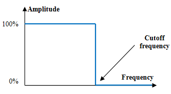
All frequencies below the cutoff frequency remain at their original amplitude. All frequencies above the cutoff frequency are completely removed.
An example finite impulse response (FIR) digital low pass filter
A typical digital finite impulse response filter a(k) computes the output signal y(n) from the input signal x(n) with the following weighted average formula.
$$y(n)=\sum_{k=0}^N a(k)\,x(n-k)$$
A good low pass filter a(k) is
$$a(k)=\begin{cases} \frac{\sin(\frac{2\pi f_c (k-\frac{N-1}{2})}{f_s})}{\pi(k-\frac{N-1}{2})}, k \ne \frac{N-1}{2} \\ 2 \frac{f_c}{f_s}, k=\frac{N-1}{2} \end{cases}$$
where fs is the sampling frequency, N is the length of the filter (the number of items in the weighted sum), and fc is the cutoff frequency.
If, for example, fs = 2000 Hz, fc = 40 Hz, and N = 201, the magnitude response of the filter will be as in the graph below.
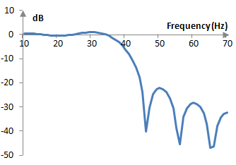
The magnitude response of this filter is not ideal. This said, the filter preserves the amplitudes of frequencies below 40 Hz almost unchanged and attenuates frequencies above 40 Hz. It is thus a low pass filter with a cutoff frequency of 40 Hz.
An example infinite impulse response (IIR) digital low pass filter
The following computation of the output signal y(n) from the input signal x(n) is an example of an impulse invariant second order low pass Butterworth filter
$$y(n)=0.22853 \, x(n-1)+1.19249 \, y(n-1)-0.42804 \, y(n-2)$$
with normalized cutoff frequency ωc = 0.6 (actual cutoff frequency equal to ωc * fs / (2π)). This filter has the transfer function
$$H(z)=\frac{0.22853 \, z^{-1}}{1-1.19249 \, z^{-1}-0.42804 \, z^{-2}}$$
Given a sampling frequency of, for example, fs = 2000 Hz, the cutoff frequency of this filter becomes 0.6 * 2000 / (2π) = 191 Hz, and the corresponding magnitude response becomes as follows.
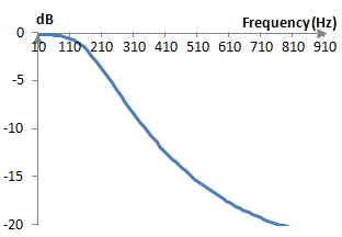
This filter preserves somewhat the amplitude of frequencies below 191 Hz and decreases the amplitudes of frequencies above 191 Hz. Although this is also not an ideal low pass filter, it is a practical low pass filter with cutoff frequency 191 Hz.
Deriving the FIR low pass filter
The desired magnitude response of an ideal low pass filter could be written as follows.
$$|H(f)|=\begin{cases} 1, -\frac{f_c}{f_s} \le f \le \frac{f_c}{f_s} \\ 0, |f| \gt \frac{f_c}{f_s} \end{cases}$$
This is an ideal magnitude response of some low pass filter with normalized cutoff frequency fc / fs. By the Nyquist-Shannon sampling theorem fc / fs < 1/2. Using a magnitude response that is symmetric around zero and includes negative frequencies is beneficial, since it allows the inverse Fourier transform below to produce a filter with real valued and not complex valued coefficients.
Denote F = fc / fs. The inverse Fourier transform of the ideal magnitude repose is
$$a(t)=\int_{-F}^F e^{2\pi j f t} df=\frac{1}{2\pi j t}(e^{2\pi j F t}-e^{-2\pi j F t})=\frac{1}{\pi t} \sin(2\pi F t)$$
The function sin(t) / t is the function sinc(t) and so FIR filters are occasionally called sinc functions. The sinc function in the equation above has ever increasing oscillations until t = 0, at which point it is a(0) = 2 F, after which it has ever decreasing oscillations. To create a discrete time filter, we will sample this continuous time function between -1 and 1 at the sampling frequency.
$$a(k)=\frac{\sin(\frac{2\pi f_c k}{f_s})}{\pi k}, k=-(f_s-1), …, f_s -1$$
We then pick a discrete filter of length N from the middle N points of the sampled a(k) and shift it to the right by (N – 1) / 2. This would produce the finite impulse response low pass filter above. In the middle of the filter, at k = (N – 1) / 2, we use L'Hopital's rule, which states that if the limits of the numerator and denominator are zero and the limits of the derivatives exist, the limit of the ratio is equal to the ratio of the limits of the derivatives.
An alternative derivation
We use the fact that applying a FIR filters to an input signals is simply a convolution of the filter with the signal. The convolution of a cosine and a sine functions of integer frequencies n1 and n2 produces zero, if the two integer frequencies are different, and something other than zero, if n1 = n2.
$$\sum_{m=0}^{f_s-1}\cos(\frac{2\pi n_1 m}{f_s}) \, \sin(\frac{2\pi n_2(k-m)}{f_s}) \approx \begin{cases} 0, n_1 \ne n_2 \\ \frac{f_s}{2} \sin(\frac{2\pi n_1 k}{f_s}), n_1 = n_2 \end{cases} $$
where one of the simple wave functions in the convolution above is restricted to an interval of unit time and is zero outside of that interval. The result is similar for two cosine and two sine functions. In other words, the convolution of a signal with a properly bound simple cosine or a sine wave would return that same wave in the signal, if the wave exists, and will return zero otherwise. This means that we can design a filter by summing up all simple waves that we want the filter to preserve.
$$a(k)=\sum_{m} \cos(\frac{2\pi m k}{f_s}), m \lt f_c, k=1, …, f_s-1$$
Since we are summing integer frequencies, we can use the following identity, known as the Dirichlet kernel.
$$1+2\sum_{m=1}^M \cos(mx)=\frac{\sin((M+\frac{1}{2})x)}{\sin(\frac{x}{2})}$$
We compute
$$a(k)=\frac{1}{2}(\frac{\sin(\frac{2\pi(f_c+\frac{1}{2})k}{f_s})}{\sin(\frac{\pi k}{f_s})}-1), k=1,..., f_s-1$$
We note that the convolution of two simple waves with the same frequency produces the same wave, but with amplitude scaled by fs / 2. Thus, we scale the filter by 2 / fs. We also note that the filter above cannot be computed at k = 0, since the sine in the denominator would produce zero. We use L'Hopital's rule again. We also center the filter so that its peak is in the middle.
$$a(k)=\begin{cases} \frac{1}{f_s}(\frac{\sin(\frac{2\pi(f_c+\frac{1}{2}) (k - \frac{f_s-1}{2})}{f_s})}{\sin(\frac{\pi (k-\frac{f_s-1}{2})}{f_s})}-1), k=1,..., f_s-1, k \ne \frac{f_s-1}{2} \\ \frac{1}{f_s} (2 (f_c+\frac{1}{2})-1), k=\frac{f_s-1}{2} \end{cases}$$
Last but not least, this filter is simply too long. Every output sample produced with this filter would require fs computations. We would prefer a shorter filter of N points.
$$a(k)=\begin{cases} \frac{1}{f_s}(\frac{\sin(\frac{2\pi(f_c+\frac{1}{2}) (k - \frac{N-1}{2})}{f_s})}{\sin(\frac{\pi (k-\frac{N-1}{2})}{f_s})}-1), k=1,..., f_s-1, k \ne \frac{N-1}{2} \\ \frac{1}{f_s} (2 (f_c+\frac{1}{2})-1), k=\frac{N-1}{2} \end{cases}$$
This formula is an approximation of the first formula above. At fs = 2000 Hz, N = 101, and fc = 40 Hz, for example, the magnitude response of the first filter above (blue) and the filter here (red) are almost identical.
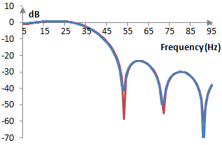
The second filter is, in essence, derived using the discrete Fourier transform and is hence less precise.
Deriving the infinite impulse response low pass filter
IIR low pass filters are also typically derived from their desired magnitude response. For an example of how IIR low pass filters are derived, see the topic Butterworth filter.
Add new comment