admin: First posted on 2012 07 27
Guest post by Anton Kamenov
Filters and other DSP operations for audio are discussed at length on this site. There are various DSP operations and the discussion below applies to all, although when engineers talk about DSP errors, they usually discuss filters – finite impulse response filters, infinite impulse response filters, etc.
DSP errors and quantization
It is worth noting that we can run into are several types of errors when designing DSP. First, an operation may have an incorrect or, more often, imprecise specification. An imprecise filter specification, for example, may result from the rounding of filter coefficients. These errors are usually barely noticeable. For example, an error four digits after the decimal in one of the coefficients of the third order Bessel high pass filter with a cutoff frequency of 6000 Hz produces no noticeable changes in the frequency response of a signal sampled at 44.1 Hz after 20 seconds. Either way, it would be good to pay attention to precise filter specifications.
Errors may be the result of computational precision. Contemporary software, however, typically has precision to at least about 15 points after the decimal for 8-byte floating representations and about 7 points after the decimal for 4-byte floating representations. Such errors are probably similarly unnoticeable.
Still other errors result from quantization. In digital signal processing, quantization is the mapping a large set of values into a smaller set. In audio, this typically means the sampling that is used to map an analogue signal that can take an infinite number of values at an infinite number of points to a discrete signal that takes a finite number of values. CD quality audio, for example, uses 16-bit signed integer representation and represents audio data with the integer numbers between -32768 and 32768. Thus, if DSP computations use the CD audio representation, the signal will be rounded (up or down) or simply truncated (down) to these integer values when processed.
Quantization can pose problems in two ways. First, we can have improper DSP processing. In an IIR filter, for example, it would be improper to round or truncate the values of the output signal, before work on that output signal is complete. In other words, it would be inappropriate to round the value of y(k – 1), until that value has already been used for y(k), y(k + 1), etc. It is easy to imagine, that such errors may accumulate in an IIR filter, if it feeds erroneously computed output back into the input. With the 16-bit integer representation, the same third order Bessel filter from example above produces a change in the magnitude response after 20 seconds of data of approximately -0.002 dB around the cutoff frequency and somewhat less in the pass band. Although this change is small, it is noticeable. In addition, we can expect that the impact of the error would be larger with longer audio data, higher sampling frequencies, or lower resolution.
Second, quantization is sometimes unavoidable. CD quality audio would ultimately contain rounded or truncated data. The impact of such truncation would be difficult to examine visually with the 44100 Hz sampling 16-bit representation and so let's use a lower sampling rate and bit rate example. Consider the 2 Hz wave (blue) sampled at 100 Hz and encoded with a 4-bit representation (red). Although the true value of the wave at sample 5 is 4.702, it has been recorded as 5. Although its true value at sample 6 is 5.476, it has also been recorded as 5. As in the figure below, it is impossible to record the wave at its true value with the given sampling resolution of 4 bits.
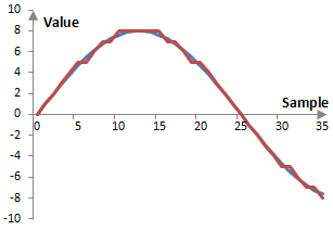
Experts may argue whether such quantization errors are audible in an audio recording (quantization errors are very obvious in some digital images, such as GIF files, where the color resolution allows only 256 colors). In any case, it is clear that such errors are systematic, quantifiable, and unavoidable. If the signal in the figure above repeats indefinitely, the error will also repeat indefinitely, in exactly the same fashion. This kind of error then is periodic with the same periodicity as the signal and is correlated to the signal. In other words, the error is a harmonic distortion of the signal.
Quantization errors are equally likely to appear in all DSP operations and they may already exist in the recorded signal. Since these errors are small, if they are audible, it is more likely that they would be audible in an audio signal recorded at low levels, when the levels of the audio signal are raised. Finally, these errors are specific to the sampling frequency, bit resolution, and signal. Different errors may manifest themselves with different signals, different sampling frequencies, or different sampling resolutions.
Dithering
Since quantization errors are unavoidable, the best thing to do is to make them non-systematic. Non-systematic errors would not be a harmonic distortion to the signal. We do so by introducing random noise in the signal of similar magnitude to the error. Dithering is the process of introducing random noise into the system to remove errors that are correlated to the signal.
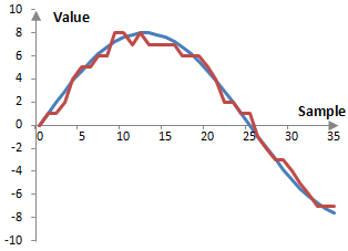
While dithering does not remove errors, it at least ensures that such errors are no longer correlated to the signal. If we introduce dithering to the signal in the figure above, we might get something similar to the figure below. This figure is the result of randomly choosing whether to round up or down each value of the wave. This is equivalent to adding a random number to the wave between -0.5 and 0.5 and then rounding up or down as appropriate. This is the simplest type of dithering – one that uses a uniform distribution of the random change to the error and is done with the sampling frequency.
There are several ways in which the dither can be changed. First, this dither uses a uniform distribution of the added error and hence it is said to have a rectangular probability density function – it is an RPDF dither. Common dithers in audio processing are the RPDF dither and the triangular probability density function or TPDF dither (RPDF dither is said to make the first moment of the error uncorrelated and TPDF is said to make the first and second moments of the error uncorrelated). Other probability density functions are possible as well.
The dither can also be changed by introducing errors with a different frequency, which is usually known as dither coloration. The purpose of this is typically to introduce dither with frequencies that are outside of the range, where the ear is most sensitive, say, outside of 1 KHz to 5 KHz (Although we should note that the threshold of hearing curves (Fletcher-Munson curves) are always dependent on the signal level and there is no interval of ear sensitivity that is independent of the level of the signal). This can be done by simply filtering the random dither. This is also referred to as noise shaping, although there is a difference between dither coloration and noise shaping. Noise shaping can be applied to reshape the inherent quantization errors without introducing dither at all.
Finally, we can modify the amplitude of the dither. The dithered signal in the figure above changes the original quantized signal by adding a bit at random samples, subtracting a bit, or leaving the bit representation of the signal unchanged. In other words, this dithering works by changing the lowest – least significant – bits of the signal and is thought of as a least significant bit or LSB operation. It is typical to use noise of one or two of the least significant bits.
Dithering should not be over-used and should not be used arbitrarily. First, there are no quantization errors when there is no signal. We should not introduce random noise if there is no systematic noise, such as between audio tracks. Alternatively, we should use a dither that is designed in such a way that it settles at zero when the signal settles at zero. Finally, dithering would usually not be applied to signals which are subject to further processing, since there may be interactions between the dither in these signals and dithers applied later.
An example of noise shaping
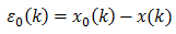
Noise shaping can be applied during quantization when the error is known. Suppose that the signal x0(k) is to be quantized as the signal x(k) and the error before any noise shaping is ε0(k).
We can apply any filter on the error ε(k) and create a new quantized value X(k), such as the following.
Perhaps you recognize that the new error ε(k) is computed with the impulse invariant second order low pass Butterworth filter with angular cutoff frequency of 0.6.
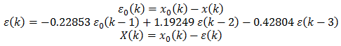
In practice, it is more common to reduce computations by using
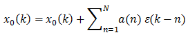
where a(n) are some filter coefficients for the filtered error. In the simplest case, the formula
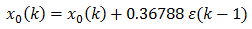
translates to the error terms being computed as in
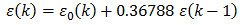
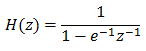
This is essentially the first order impulse invariant low pass Butterworth filter with cutoff frequency 1.
Add new comment