admin: First posted on 2013 09 06
This is the second post in a series of articles about deconvolving a reverberated sound to get the impulse response of natural reverberations and then using this impulse response as the artificial reverb. In the previous post we created the impulse response of an example reverb. In this post we will take a short sound – a drum hit – and we will reverberate it with the impulse response developed before. Later, we will take the reverberated drum and we will pretend that we do not know the impulse response. We will try to recreate the impulse response and see how well we do. As a reminder, it should be possible to record the natural reverb of a short sound, such as a drum hit, in a room or a hall and to deconvolve this natural reverb to create an artificial reverb.
A short drum sound may look something like this.
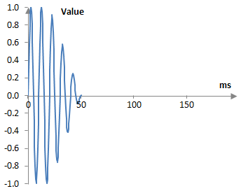
This is, of course, a fake drum hit. A real drum hit may be longer than 50 ms. In the real world, a longer wave recorded at the 44.1 KHz standard sampling rate will also have too many samples, making the drawing of nice intuitive graphs difficult. This, this is simply a sine wave that decays, sampled at 2000 Hz. We will, however, pretend that this is the recording of a drum hit.
We can take this drum hit and run it through the same operations as last time – a two-tap delay, two Shroeder all pass filters, and a feedforward comb filter. Alternatively, we can simply apply the reverb impulse as a filter and convolve the two signals.
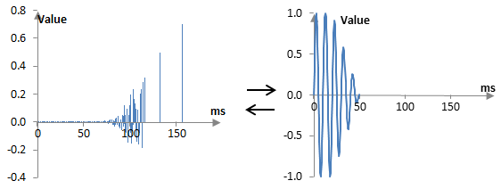
I am used to working with finite impulse response filters that are symmetric around the middle and I often forget that the impulse response has to be flipped as in the picture above, to be applied properly. The initial impulse notches (with the least delay from the original signal), have to hit the signal first. With symmetric filters this is not important – they are symmetric – but here this is needed.
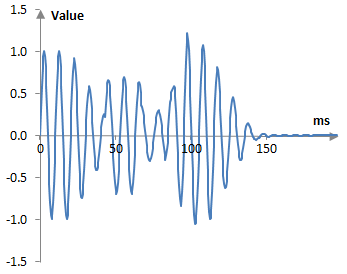
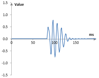
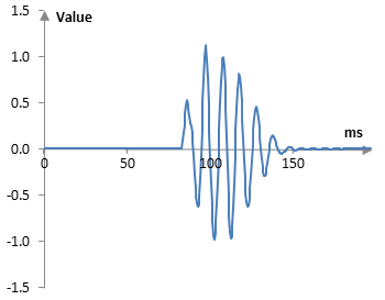
The end result will be as in the following figure (the original signal included; note the change in the scale of the vertical access). This is probably not as expected. The peaks around 100 ms are perhaps too large. This is correct however. With this specific signal and with the specific parameters of the reverb, we get some overlapping of the drum hit repetitions around 100 ms that boost the signal peaks.
We can break this result down by following the steps of the previous post. First, here is the result of the early reflections – a tapped delay line with two taps, one with a delay of 43 ms and decay of 0.7 and the second one with delay of 67 ms and decay of 0.5 (at the 2000 Hz sampling rate, the delays are 86 samples and 134 samples). The original signal is omitted from the graph below.
The following is the result of running the original signal through a Shroeder all pass filter with a delay of 3.7 ms (7 samples) and a decay of 0.7. A delay of 83 ms (166 samples) was introduced before the all pass filter.
Taking the output of the first all pass filter and putting it through the second all pass filter produces the graph below. The second all pass filter has a delay of 1.23 ms (3 samples) and a decay of 0.65. It does not look that there is much change in the signal, but this is to be expected with this signal and the small amount of delay.

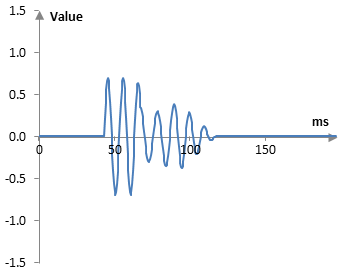
Finally, we take the output of the second all pass filter and put it through a comb. The comb filter has a delay of 11 ms (23 samples) and a decay of 0.7. Again not much difference from the previous picture, but we will obviously not see as much as we can see when working with impulses. It is, however, this comb that introduces the peak in the final signal below.
The final signal itself is the sum of the original signal, the two taps of the tapped delay line, and the output of this comb. Our next task is to take the final signal and, pretending that we do not know the exact specifications of the filters, create the corresponding impulse response.
authors: mic
Add new comment