A phase oscilloscope, also known as a "vectorscope", is a two-dimensional scatterplot of the values of one signal against the values of another signal and displays information about the amplitude, phase, and frequency content differences between two signals.
In other words, at time t, the point on the phase oscilloscope graph of two signals x(t) and y(t) is (x(t), y(t)).
Examples of figures produced by the phase oscilloscope are shown below.
- Differences in the amplitudes of the two signals will tend to skew the resulting figure by stretching it along the axis for the signal of larger amplitude.
- Differences in the phase of the two signals will also skew the resulting figure, but diagonally.
- Differences in the frequencies of the two signals will tend to produce more complex figure.
Example simple figures produced by a phase oscilloscope
When the two signals are simple sine waves, the figures produced by the phase oscilloscope are called Lissajou curves. The curves are straight lines, when the frequencies and phases of the signal are the same. Since the sine waves are periodic, the curves are closed.
Consider two simple signals in time x(t) = A sin(a t + d) and y(t) = B sin(b t). By definition, A is the amplitude of the signal x(t), a is the frequency of the signal x(t), and d is the initial phase of the signal x(t), B is the amplitude of the signal y(t), and b is the frequency of the signal y(t). Since the phase of y(t) is zero, d is also the differences in initial phase between the two signals.
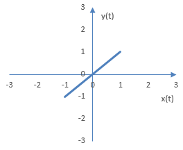
Suppose A = a = B = b = 1 and d = 0. When the two frequencies a and b are the same and the difference in phase is 0, the oscilloscope will display a line as in the figure below.
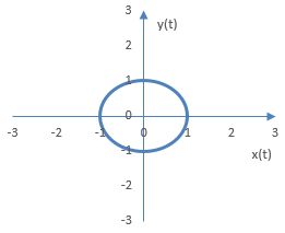
Now suppose A = a = B = b = 1 and d = π / 2. When the two frequencies a and b are the same and the difference in phase is not zero, the oscilloscope will display a circle (if the phase difference is a quarter of the frequency cycle) or an ellipse.
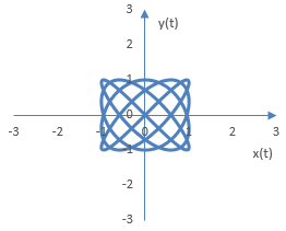
More complex phase oscilloscope figures can be produced by employing two different frequencies. The following is the phase oscilloscope figure for A = B = 1, d = 0, a = 4 and b = 5. In general, the complexity of the figure will depend on the ratio a / b.
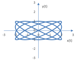
The following is the same figure, but with A = 2. Larger amplitude for the signal x(t) stretches the figure along the x axis.
Phase oscilloscope figures for complex signals
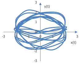
The figures produced by the phase oscilloscope for more complex signals will be more complex. In audio processing, since the signals will change with time, the figures may also not be symmetrical.
The following is an example phase oscilloscope figure produced with two complex signals, each consisting of two sine waves, with a gradual increase in amplitude in one of them and some random noise in the second. Amplitudes, phase, and frequencies in these two signals differ.
A phase oscilloscope graph for an actual sound sample is provided in Orinj Phase oscilloscope.
Add new comment