The general form of a digital feedforward comb filter is
$$y(k) = x(k) + w x(k – M)$$
where y(k) is the output signal at sample k, x(k) is the input signal at sample k, w is some scalar, a M is some positive integer.
The general form of a digital feedback comb filter is
$$y(k) = x(k) + w y(k – M)$$
Feedforward comb filters
Suppose that a feedforward comb filter is defined by the equation
$$y(k) = x(k) + 0.8 x(k – 50)$$
This filter computes the output signal as the sum of the input signal at the current sample at its current amplitude plus the input signal 50 samples ago with amplitude that is 0.8 of the original amplitude. This filter thus is a simple delay. The output signal is the same as the input of the signal plus a repetition of the input with a delay in time and decay in amplitude. In this particular example, the delay is 50 samples, which given a sampling frequency of fs Hz would translate to 50 / fs seconds, and the decay (the loss of amplitude) is 20%.
Feedforward comb filters are simple delays, which produce the sum of the input signal and a delayed and decayed repetition of the input signal.
The transfer function of the feedforward comb filter, computed with the Z transform, is as follows.
$$H(z) = 1 + w z^{-M}$$
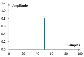
The impulse response of the example filter above is obvious and is shown in the graph below.

The magnitude response of the feedforward comb filter is given by the formula
$$|H(e^{j\omega})|=\sqrt{(1+w^2)+2w\,\cos(\omega M)}$$
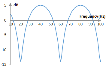
where ω is the angular frequency in radians per second. The magnitude response of the example filter above, given a sampling frequency of 2000 Hz, is the following.

This magnitude response is what gives the filter its name – "comb filter".
Feedback comb filters
Suppose that a feedback comb filter is defined by the equation
$$y(k) = x(k) + 0.8 y(k – 50)$$
This filter computes the output signal as the sum of the input signal at the current sample at its current amplitude plus the output signal 50 samples ago with amplitude that is 0.8 of the original amplitude. We can expand the equation above as follows.
$$y(k) = x(k) + 0.8 y(k – 50)$$ $$= x(k) + 0.8 x(k – 50) + 0.8*0.8 y(k – 100)$$ $$= x(k) + 0.8 x(k – 50) + 0.8*0.8 x(k – 100) + 0.8*0.8*0.8 y(k – 150)$$ $$= …$$
This filter thus produces the sum of the input signal plus a number of repetitions of the input signal with ever decreasing amplitude and with an ever increasing delay. This filter thus is a simple echo. The echo in this specific example has a delay of 50 samples (or 50 / fs seconds if the sampling frequency is fs samples per second) and decay (loss of amplitude) of 20%.
Feedback comb filters are simple echoes, which produce the sum of the input signal and a number of repetition of the input signal with ever decaying amplitude and an ever increasing delay. The decay and the decay between each two neighboring repetitions are always the same.
Since the output signal is fed back into the input of the filter as in the general formula at the top of the article, this filter is a "feedback" filter. For those same reasons this filter is an infinite impulse response filter (IIR). The impulse response of the filter has notches that theoretically continue forever.
The transfer function of the feedback comb filter is as follows.
$$H(z)=\frac{1}{1-w z^{-M}}$$
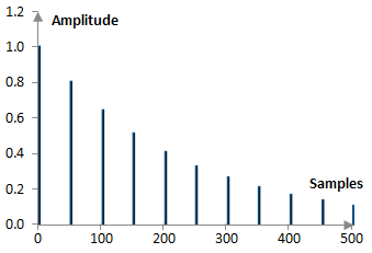
The following is a portion of the impulse response of the example filter above. Note that the impulse of this filter is not finite and thus this is just a portion over the first 500 samples.

The magnitude response of the feedback comb filter can be computed from its transfer function.
$$|H(e^{j \omega})|=\frac{1}{\sqrt{(1+w^2)-2w \, \cos(\omega M)}}$$
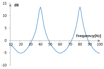
where ω is the angular frequency in radians per second. The magnitude response of the example filter, at sampling frequency of 2000 Hz, is the following.

Periodicity of the magnitude response
The notches of the two filters occur every 40 Hz. This is to be expected, as given the sampling frequency of 2000 Hz, both filters delay the signal by 40 Hz = 2000 Hz / 50 samples. The notches will become more frequent with a larger delay and less frequent with smaller delays.
The periodicity of the magnitude responses of both feedforward and feedback comb filters can also be seen in the magnitude response formulae derived from the transfer functions. The periodicity comes from the term cos(ω M). In terms of angular frequencies, we can expect periods of 2 π / M.
Using comb filters
Feedforward comb filters produce simple delays. Several such filters can produce, say, a multitap delay. Feedback comb filters, as we can see above, produce an echo. Several such filters can produce a multitap delay with feedback. Comb filters are also useful in designing artificial reverbs, as reverberations are simply a multitude of echoes (see Shroeder reverb).
Add new comment