In signal processing, the impulse response of equipment or software is a graphical, numerical, or mathematical representation of the output signal (usually, the amplitude of the output signal) of that equipment or software after an impulse is sent to it as the input signal.
Impulse
An impulse is a signal that is zero everywhere except at a specific point of time. Simplistically, an impulse is an instantaneous pulse in an otherwise zero signal.
Take, for example, the following digital signal.
…, 0, 0, …, 0, 1, 0, …, 0, 0, …
This signal consists of zeroes, except for a single 1 at one of the samples. This signal is an impulse.
In mathematics, the Dirac delta function (the "unit impulse function") is a function that is zero everywhere except at zero, where it is infinitely large. In the discrete realm, the Kronecker delta function of two integers is zero everywhere except when the two integers are equal. Both functions are examples of impulse functions.
The Kronecker delta function is also sometimes defined as a function of one integer argument and with values of zero everywhere, except at zero, where it is equal to one.
$$\delta(i)=\begin{cases}0, i \ne 0 \\ 1, i=0 \end{cases}$$
The Kronecker delta function will produce the example digital signal above.
Impulse response
When an impulse is an input to a system – equipment, software, and so on – the system will produce some output signal. This output signal is the impulse response of the system.
In the first example below, when an impulse is sent through a simple delay, the delay produces not only the impulse, but also a delayed and decayed repetition of the impulse. This is what a delay – a digital signal processing effect – is designed to do. The impulse response is the output signal, which consists of an impulse and a delayed and a decayed impulse.
The second example below is the impulse response of an actual bass amplifier and speaker combo. A bass combo will not reproduce an impulse perfectly, as it will also add the reverberations of the chassis, some frequency coloration from the amplifier and speaker, and so on. Thus, the impulse response of the bass combo is not just an impulse, but something more complex.
Example: impulse response of a simple delay
A simple delay takes a signal and creates one delayed and decayed (with lower amplitude) repetition.
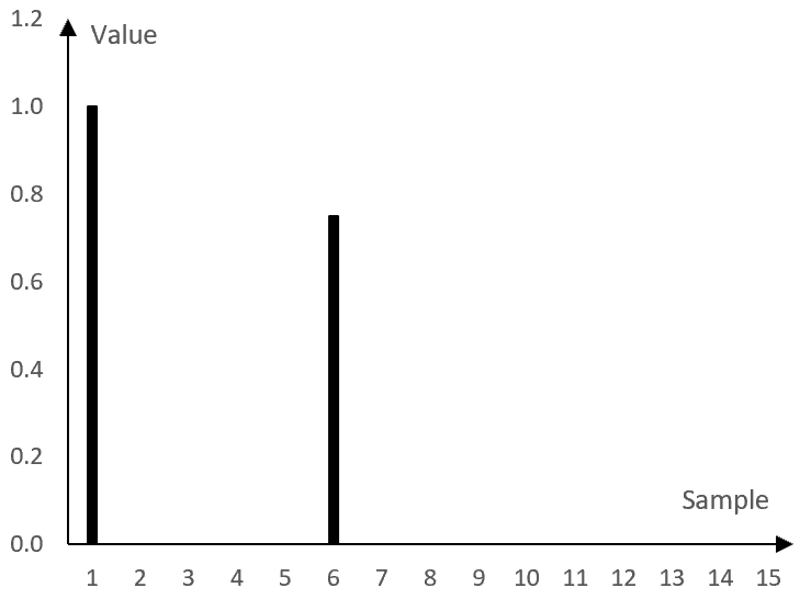
If, for example, the delay repeats a signal with a delay of 5 samples and with 75% of its original gain, then the delay will produce the following output from the impulse signal above (including the original signal).
…, 0, 0, …, 0, 1, 0, 0, 0, 0, 0.75, 0, …, 0, 0, …
This is the impulse response of the delay. The graphic representation of this impulse response is as follows.
Using an impulse response
We can use the impulse response of the simple delay above to compute what any signal will become after being processed through the simple delay. This computation is shown in the following graph.
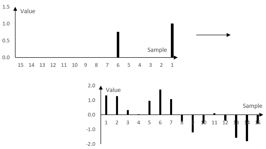
In this graph, the impulse response of the example simple delay is on top. The values of an example signal are below.
To compute the output of the simple delay, we multiply the samples of the example signal (bottom) by the samples of the impulse response (top) – reversed as in the graph above – and we sum the result. At the specific position displayed in the graph above, the value of the signal at sample 7 is multiplied by the first, larger notch of the impulse response. The value of the signal at samples 6, 5, 4, and 3 are multiplied by zero, as there are no corresponding impulse response notches (the impulse response is zero there). The value of the signal at sample 2 is multiplied by the second notch of the impulse response, and so on. All resulting values from the multiplications are summed.
In other words, the value of the output signal at this sample is equal to the value of the input signal at sample 7 with gain 1 plus the value of the input signal at sample 2 with gain 0.75. This computation is what we expect the computation to be for a simple delay with the delay of 5 samples and the decay specified by the 75% gain.
To compute the value of the output signal at the next sample, we shift the impulse response one sample to the right. The value of the output signal at the next sample will be equal to the value of the input signal at sample 8 with gain of 1 plus the value of the input signal at sample 3 with gain 0.75.
This process continues until the whole input signal is traversed and all samples of the new signal are computed. The process itself – the summation of products (a moving weighted average) – is called "convolution". If x(k) is an input signal to the simple delay and a(k) is the impulse response of the simple delay with length N samples, then the output signal y(k) is the convolution of x(k) and a(k).
$$y(k)=x(k)*a(k)=\sum_{n=0}^{N}a(n)\,x(k-n)$$
The same process is used also with more complex impulse responses, such as the ones below.
Example: impulse response of a speaker cabinet
The following graph shows the first 10 milliseconds of the impulse response of an actual bass amplifier and speaker combo. The horizontal axis shows the time in seconds and the vertical axis, as before, is the value of the impulse response.
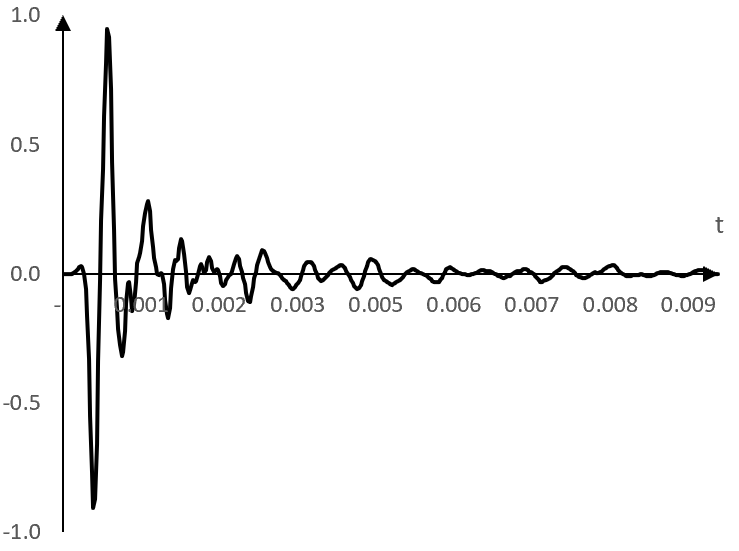
While this impulse response is more complex than the impulse response of the simple delay above, it can be used in the same way. The convolution of this impulse response with a signal should simulate the impact of the bass combo on the signal. See Orinj Convolution to hear a sound sample before and after the convolution with such an impulse response.
Finite impulse response (FIR)
The following formula is the impulse response of a digital low pass filter. A low pass filter is designed to pass low frequencies and stop high frequencies, below and above some frequency called the "cutoff" frequency.
$$a(k)=\begin{cases} \frac{\sin(2\pi \frac{f}{f_s} (k-\frac{N-1}{2}))}{\pi (k-\frac{N-1}{2})}, \, k \ne \frac{N-1}{2} \\ 2 \frac{f}{f_s}, \, k = \frac{N-1}{2} \end{cases}$$
Here, k are the samples, N is the length of the impulse response in number of samples, fs is the sampling frequency, and f is the cutoff frequency (the frequency around which the low pass filter transitions from a filter that passes the low frequencies to a filter that stops the high frequencies).
Since this impulse response can be applied to a signal with the same process above – convolution – the values of the impulse response a(k) act like weights in a moving weighted average. a(k) is not only the impulse response but is also called the set of "filter coefficients" or the "filter" itself.
The following is a plot of this filter for length N = 101 samples, sampling frequency fs = 2000 Hz, and a low pass cutoff frequency f = 40 Hz.
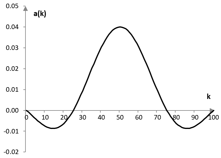
The filter is not defined outside of its N points, but could be defined as equal to 0. In practice, when using such filters, this is sometimes necessary. In a convolution, setting the filter to 0 outside of the N points does not change the output of the convolution.
The fact that the impulse response settles to zero in a finite number of points (N in this example) is what makes this filter a "finite impulse response" filter or FIR filter.
Infinite impulse response (IIR)
Consider the example Butterworth low pass filter.
$$y(k)=0.245\,x(k-1)+1.1581\,y(k-1)-0.4113\,y(k-2)$$
In other words, the output value y(k) at sample k is equal to the weighted sum of the input value at the previous sample x(k – 1), the output value at the previous sample y(k – 1) and the output value two samples before y(k – 2).
This filter is "recursive", which means that its values depend not only on the input to the filter x(k), but also on its previous outputs y(k). Sending an impulse through this filter will produce the following impulse response.
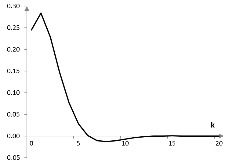
This impulse response has the potential to be infinitely long and never settle to zero. This filter is an "infinite impulse response" filter or an "IIR" filter. In practice, digital signals can only take a finite number of amplitude values and so this filter will have to settle to zero at some point if it settles at all. Nonetheless, it is called an IIR filter.
Impulse responses as a description of the system
When the impulse response is defined by a function such as in the previous two examples, the function is called an "impulse response function".
In all examples here, the impulse response (or the impulse response function) fully defines the impact of the system on a signal. In other words, the impulse response can be used to determine other properties of the system, such as its magnitude response and phase response.
The following is the magnitude response of the example bass combo impulse response. It was computed with the Fourier transform of the impulse response itself.
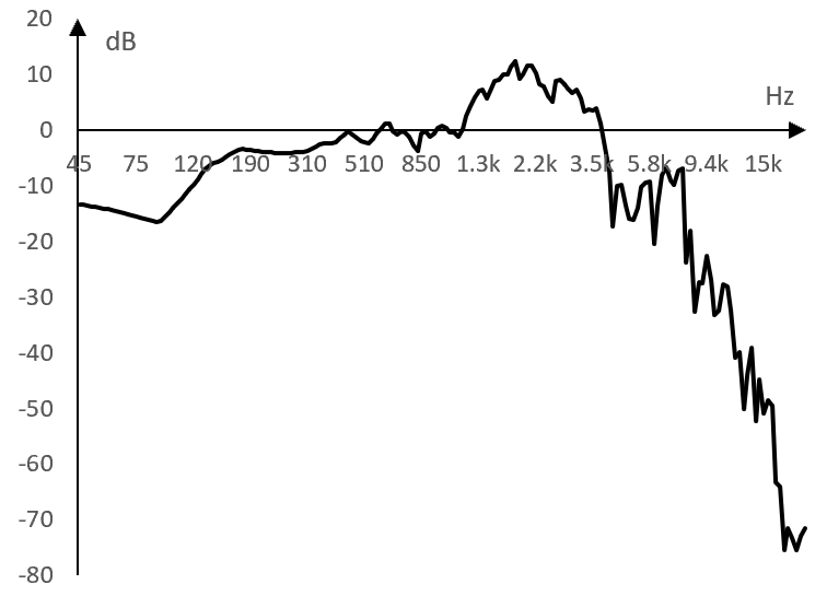
This graph tells us, for example, that the impulse response of this bass combo has a significant roll off in the magnitude of frequencies above 9-10 kHz.
Creating impulse responses
Most of the impulse responses here rely on the mathematics behind digital signal processing theory.
The impulse response of the FIR filter, for example, relies on the fact that sine and cosine functions are orthogonal for properly chosen frequencies and intervals (see Fourier analysis). Simplistically, this means that the sums of products employed by the convolution are approximately zero for two sine or cosine waves of different frequencies, but not zero for two sine waves of the same frequency or two cosine waves of the same frequency. The convolution with the impulse response will produce approximately zero for all frequencies that are in the signal, but not in the impulse response itself. The same convolution will preserve the frequencies that are both in the signal and the impulse response. Then, one way to create a filter then is to simply sum up the frequencies that the impulse response should preserve (and omit the frequencies that it should zero out). The formula above is very similar to what we will get if we follow this methodology (see Low pass filter).
The example bass combo impulse response was computed by comparing an input signal to the bass combo to the corresponding output signal from the bass combo. If the output signal is the convolution of the input signal and the impulse response of the bass combo, then the impulse response is the "deconvolution" of the output signal and the input signal. An example of this is shown in the topic Sine sweep.
The same method that was used to produce the bass combo impulse response can be used to produce impulse responses for other equipment.
Note that, in the bass combo case, since the input signal must be played through the combo and the output signal recorded, the impulse response presented above is technically not just the impulse response of the combo. It is the impulse response of the whole system, including the combo, microphone, recording equipment, and so on.
Add new comment