In practice, sound is a complex multitude of waves with different frequencies, phase, and amplitudes. When sound is recorded digitally, however, it becomes simply a collection of numbers. The properties of the many sound waves – frequency, phase, amplitude – cannot be discerned from the digitized data. In the world of audio then:
Digital signal processing, or DSP, is the science of manipulating digital signals using nothing more than what is contained in the digital representation of the signal and with little knowledge of its precise properties.
A digital audio signal is simply a set of numbers and the operations that modify these numbers to the needed end are mathematical in nature. DSP manipulates digitized signals typically with mathematical operations. It is a sizeable body of knowledge that has applications not only in music or mathematics, but also in physics, engineering, photography and video and many other fields. DSP, in fact, is such a large body of knowledge that the definition above is hardly precise. For the purposes of this site, however, it is appropriate.
The following is a simple introduction to digital signal processing with examples of simple DSP operations.
Properties of simple waves and the mathematical representation of complex signals
The wave
$$x(t)=A\,\cos(2\pi\,f\,(t-\tau))$$
has initial phase equal to τ units of time, peak amplitude equal to A, frequency equal to f cycles per unit of time, and length of cycle equal to 1/f units of time. The three properties – amplitude, phase, and frequency (or length of cycle) – fully define a simple cosine wave as a function of time.
When this wave is digitized, its value is recorded at various points of time. This process is called sampling. The number of samples taken in an interval of time is called the sampling rate. Commonly, sampling is at uniform time intervals and the sampling rate is constant. It is also common to record samples with comparable amplitude, called the sampling resolution. Sampling with a constant sampling rate and sampling resolution simplifies DSP and is called pulse code modulation or PCM.
Suppose that we sample the simple wave A cos(2π f (t – τ)) over the time interval T with the sampling frequency fs. The times at which a sample is taken are t = 0, 1/fs, 2/fs, 3/fs, and so on. If these samples are numbered with k = 0, 1, 2, …, then the value of the wave at each sample will be
$$x(k)=A\,\cos(2\pi\,f\,(\frac{k}{f_s}-\tau))$$
In τ seconds, there would be m ≈ τ / T = τ fs samples taken and so we can, with some approximation, rewrite the above formula as follows.
Given the sampling frequency fs, the wave
$$x(k)=A\,\cos(\frac{2\pi\,f\,(k-m)}{f_s})$$
has initial phase of m samples or m / fs units of time, peak amplitude of A, and frequency of f. Its cycle is 1/f units of time or fs / f samples. Again, the three properties – amplitude, phase, and frequency – fully define a simple cosine wave as a function of time. (Note here one of the most important theorems in DSP – the Nyquist-Shannon sampling theorem. In one of its many versions, the theorem states that the frequency content of a signal is fully represented by sampling at a certain frequency, if the signal does not contain frequencies higher than one-half of the sampling rate. That is, only waves with frequencies up to half of some sampling frequency can be recorded digitally with that sampling frequency.)
Practical signals are often thought of as a sum of many simple waves. A continuous complex signal x(t) can be written as follows.
$$x(t)=\sum_{n=0}^{N-1} A_n\,\cos(2\pi\,f_n\,(t-\tau_n))$$
An, fn, and τn are the peak amplitude, frequency, and initial phase of each of the n simple waves in the signal.
A discrete time complex signal x(t), sampled with the sampling frequency fs, would be
$$x(k)=\sum_{n=0}^{N-1} A_n\,\cos(\frac{2\pi\,f_n\,(k-m_n)}{f_s})$$
When processing digital signals, we will work with signals for which we do not know the precise values for N, An, fn, and mn or τn. As above, the task of DSP is to manipulate x(k) without knowing these values.
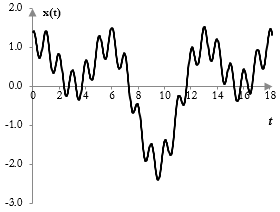
The signal in the figure below, for example, consists of three simple waves. We can tell that the signal contains at least a higher frequency with smaller amplitude and some lower frequencies. It is impossible to tell, however, that there are exactly three frequencies and that they are exactly the simple waves cos(t), cos(0.5 t), and 0.4 cos(2π t).
Practical signals
One fundamental question remains: Whether all complex signals consist of simple waves. We do not actually know whether practical signals resemble sine or cosine waves in any way.
As it turns out, whether practical signals are the sums of simple sine and cosine waves is not important. In 1807, Joseph Fourier showed that any periodic function with a period of 2π that is integrable over [-π, π] can be approximated with a (potentially infinite) linear sum of sine and cosine waves (see Fourier analysis). With some adjustments to Fourier's theory, similar approximations can be done for other periods and intervals. We can continue to treat complex signals as sums of simple waves, whether or not they are such in practice.
Simple DSP operations
The mixing of music – the combination of several audio tracks into one – is one of the simplest DSP operation. Take a recording that consists of four tracks that are yet not mixed: drums, bass, guitar, and vocals. Each track contains a sampled signal and there are four sampled signals, which we will label with xd(k), xb(k), xg(k), and xv(k) for the drums, bass, guitar and vocals respectively. We can mix the tracks into a single music piece if all tracks, when recorded digitally, are sampled with the same sampling frequency and that volumes, pans, envelopes, and various effects for each track have already been set and no other adjustments should be made. The output of the mixing process y(k) is the signal
$$y(k)=x_d(k)+x_b(k)+x_g(k)+x_v(k)$$
The simplest delay DSP effect is one in which the signal is repeated once with some delay in time and some decay in amplitude. The output y(k) of the digital simple delay can be computed with the following equation.
$$y(k)=x(k)+A\,x(k-m)$$
The output signal y(k) is the sum of the input signal x(k) and the same input signal x, but this time delayed by m samples and with amplitude scaled by A. Given the sampling frequency fs, the delay of m samples is equivalent to a delay of m / fs units of time. This operation is also known as a feedforward comb filter.
Consider the following computation of the output signal y(k) from the input signal x(k).
$$y(k)=\begin{cases} 0.75, & |x(k)| \ge 0.75 \\ x(k), & |x(k)| \lt 0.75 \end{cases}$$
This operation is known as a hard clip distortion.
More complex DSP operations
None of the simple DSP operations above make use of the fact that complex signals consist of simple sine waves. More complex DSP operations do.
Most complex DSP operations rely on a couple of simple facts. First, the sumproduct (and convolution) of two simple waves at different frequencies is zero for appropriately chosen intervals (i.e., simple waves are orthogonal). Second, the sumproduct (and convolution) of two simple waves at the same frequency is constant for appropriately chosen intervals. This makes it easy to extract simple waves from complex signals and, in fact, discern their amplitude and phase. This is explained in the topic Fourier analysis. Relatively simple examples of the application of these facts is the alternative derivation of the low pass filter and the interpretation of the Fourier transform on this site.
Of course, not all DSP relies on the facts above. See for example, data compression of digital signals with the Haar wavelets or the Daub4 wavelets. Note, however, that the wavelets themselves satisfy the same properties – they are orthonormal – and that they also may act as low pass and high pass filters on the signal.
Add new comment