A phaser is a sound effect similar to a short delay or a chorus, but with distinct wah wah qualities. The effect is achieved by combining the output of a sequence of all pass filters with the original signal. The filters change in the phase of frequencies in the signal and thus reduce the magnitude of selected frequencies. The filters also vary the frequencies for which these magnitude reductions occur and this variation is similar to a wah wah.
Example phaser and sound sample
See Orinj Phaser to hear a sound sample before and after a phaser.
Phaser construction
A phaser combines the input signal with the output of a sequence of all pass filters with oscillating decays. Example all pass filters are below.
- The all pass filters change in the phase of frequencies in the signal. Because of this, when the result is combined with the original, the amplitude of some frequencies decreases, while the amplitude of other frequencies is preserved. The magnitude response of the total effect is similar to that of a short delay or a comb filter. It has peaks, where the magnitude of frequencies is preserved, and notches, where the magnitude of certain frequencies is significantly reduced.
- The parameters of the all pass filters vary over time. This causes the notches in the magnitude response of the phaser to oscillate, moving left and right. This movement produces a wah wah sound.
The phaser has two qualities – a short delay type coloration of the sound and the oscillating wah wah effect. Which of those qualities is more noticeable depends on the number, type, and placement (in the frequency spectrum) of the filters and of the speed and magnitude of the oscillation in the filter parameters. The wah wah effect, for example, may not be noticeable, if the oscillation is really slow.
Phaser parameters
- Rate, modulation, or LFO: At a minimum, a phaser will allow for control over the frequency of the oscillation in the filters.
- Gain or dry and wet mix: Most phasers will allow control over the relative gain applied to the original signal vs. the gain on the output of the sequence of filters.
- Spread or Q factor: More flexible phasers could control the spread of the notches in the magnitude response (see Equalizer for a description of the term Q factor).
- Depth or sweep: Some phasers may allow control over the amplitude of the oscillation.
- Center, sweep, or width: Some phasers may allow control over where the notches in the magnitude response are centered.
- Stereo, feedback, or rotation: Some phasers may allow for feedback between channels.
A phaser may also use a single control to modify a number of these parameters together, based on the preference of the designer.
An example continuous all pass filter for a phaser
The following is the transfer function of a continuous time all pass filter that can be used in a phaser.
$$H(s) = \frac{s-\omega_0}{s+\omega_0}$$
This is a first order all pass filter.
This is indeed an all pass filter, as its magnitude response is
$$H(j \, \omega) = |\frac{j \, \omega-\omega_0}{j \, \omega+\omega_0}|=|\frac{-(\omega_0-j \, \omega)^2}{\omega^2+\omega_0^2}|$$ $$=|\frac{\omega^2+2\,j \, \omega_0 \, \omega-\omega_0^2}{\omega^2+\omega_0^2}|=|\frac{\sqrt{(\omega^2-\omega_0^2)^2+(2 \, \omega_0 \, \omega)^2}}{\omega^2+\omega_0^2}|=1$$
The phase response of this filter is
$$\Theta(\omega)=\mathrm{atan2}(\frac{Im(H)}{Re(H)})=\mathrm{atan2}(\frac{2\,\omega_0 \, \omega}{\omega^2-\omega_0^2})$$
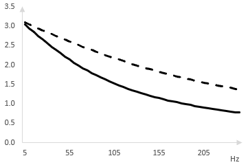
This phase response is π at ω = 0, decreases to &pi / 2 at ω = ω0, and decreases thereafter as ω increases. The following is a graph of the phase response between 0 Hz and 250 Hz for ω0 = 100 Hz (solid line) and ω0= 200 Hz (dashed line).
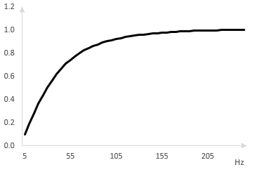
The phase shift of the all pass filter is important. Adding the output of the all pass filter to the original signal means adding two signals with different phase. The magnitude of frequencies in the result changes depending on the phase shift. The lower the frequency, the closer the phase shift to π, the closer the output of the all pass filter is to a wave with an inverted phase, the lower the magnitude of the result. Adding the output of the all pass filter to the original signal creates a high pass filter. A graph of this is shown below.
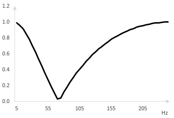
The high pass filter is the result of adding the original signal to the output of a single all pass filter. A sequence of several all pass filters creates a more complex magnitude response. The response is one where certain bands of frequencies are preserved while other bands of frequencies are attenuated, creating notches in the response. The notches shift when the parameters of the all pass filters vary, which is how the phaser works. This is shown below.
This is an example all pass filter and other all pass filters are possible.
An example discrete all pass filter
Use the bilinear transformation to create a discrete digital all pass filter from the continuous filter above.
$$s=\frac{2(z-1)}{z+1}$$ $$H(z)=\frac{\frac{2(z-1)}{z+1}-\omega_0}{\frac{2(z-1)}{z+1}+\omega_0}=\frac{(2-\omega_0)z-2-\omega_0}{(2+\omega_0)z-2+\omega_0}$$
Set d = (2 - ω0) / (2 + ω0). Note however that the bilinear transformation warps the frequency response and account for that by replacing ω0 with 2 tan(ω0 / 2) (see Bilinear transformation).
$$H(z)=\frac{d-z^{-1}}{1- d\, z^{-1}}, \, \, d=\frac{1-\tan(\frac{\omega_0}{2})}{1+\tan(\frac{\omega_0}{2})}$$
This filter computes its output y at sample k from the input x as follows.
$$y(k)=d \, x(k)-x(k-1)+ d \, y(k-1)$$
d is a constant that multiplies the current sample of the input x and so we can call it the decay of the filter. (This is essentially is a special case of the Shroeder all pass filter described in the topic All pass filter).
An example phaser
We use the discrete all pass filter above to create a phaser. We start by examining the output of a phaser with only one all pass filter and then add more all pass filters.
The following is the magnitude response of a phaser with only one first order all pass filter. As expected, combining the original signal with the output of a single all pass filter simply works like a high pass filter. In this example, we set ω0 = 50 Hz (the sampling rate is 500 Hz).
Suppose instead that we use two all pass filters in sequence. The output of the first all pass filter becomes the input to the second all pass filter. The output of the second all pass filter is combined with the original signal to produce the output of the phaser. We spread out the two all pass filters with ω0 = 50, 100 Hz respectively. The magnitude response of the phaser is as follows.
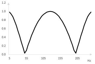
We add two more all pass filters. The following is the magnitude response of a phaser with four all pass filters, spread at ω0 = 50, 100, 150, and 200 Hz.
Oscillation in the phaser
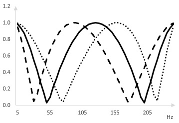
As the center frequencies of the all pass filters oscillate (left and right), the notches in the magnitude response shift (left and right respectively). The following is the same magnitude response (solid), shown when the center frequencies of the all pass filters are shifted to the left by 25 Hz (dashed) and to the right by 25 Hz (dotted).
Add new comment